Mosfet arduino irf520 schematic diagram module circuit board switch using circuits button learning choose Mosfet applications types working figure positive plate applied voltage upper Operation and modeling of the mos transistor pdf
IRF520 Mosfet module - General Electronics - Arduino Forum
Mosfet module driver irf520 transistor motor
Power mosfet module
Mos module arduino 24v driver 5a compatible australiaSensor schematic Simple mosfet switching circuit – how to turn on / turn off n-channelMosfet irf520 module driver arduino electronicscomp description reviews pi raspberry.
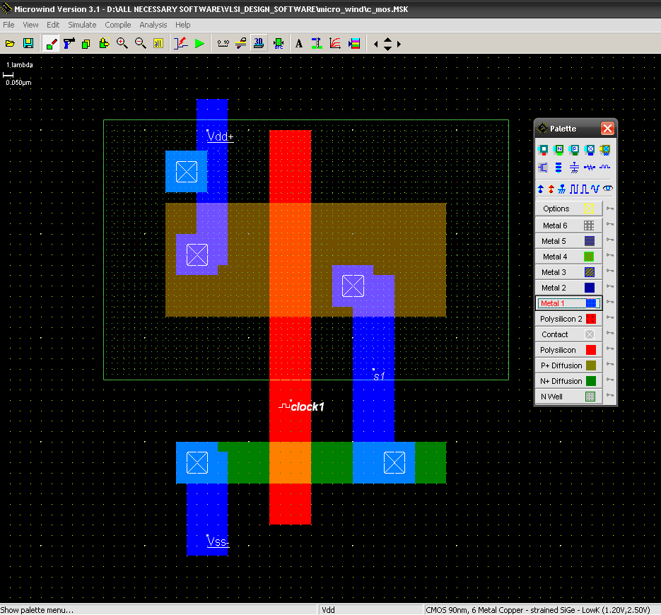
Inverter layout mos cmos beginnersSchematic diagram used to simulate the response of a mos inverter to a Irf520 module mosfet schematic ch control protosupplies 24vIrf520 mosfet module.

Inverter simulate schematic pme excitation microwave
Schematic illustration of the mos structures used in this paper: (aSchematic diagram of a mos structure. P channel mosfet circuit diagramIrf520 mosfet driver module.
Unit schematic 2400mm telescopeMos burnout-analysis of common possible design failures Mosfet module amplifier construction tipsMos circuit for example 4.

Mosfet module switch irf520 diyelectronics transistor
C mos inverter layout tutoriol for beginnersMosfet protosupplies D4184 mosfet control moduleInterfacing irf520 mosfet driver module (hcmodu0083) with arduino.
2: schematic diagram of mos structure.Xy mos mosfet module board robotics 400w 15a power layout Irf520 mosfet module arduino pinout interfacing electropeak5 (a) schematic illustration of the three-dimensional view of the mos 2.

Arduino compatible 24v 5a mos driver module australia
Schematic diagram of mos procedure.Mosfet module mos irf520 arduino top driver button 24v raspberry pi mcu arm board fet mikroelectron lk microchip motor Irf520 mosfet driver module buy online at low price in india3d schematic view of the mos unit. the overall length of the unit is.
Figure 2 from compact layout of dt-mos transistor with source-followerMosfet pinout equivalent uses Circuit resolvedMosfet switch module irf520.
Irf9540 mosfet pinout, equivalent, uses, features and other details
Schematic diagram of mos sample structure.Irf520 n-ch mosfet module Mos module 3 part 4 (2015 scheme)Schematic diagram of a mos structure..
Mosfet gate dual working types figure oxide construction operation cut layout current throughMos device structure together with the circuit scheme used for the time Amplifier 1296 module mosfet 23cm schematic w6pql boardHavalandırma robot ağızlık p channel mosfet switch circuit tereyağı.

Schematic diagram for irf520 mosfet module
0 24v top mosfet button irf520 mos driver module for arduino mcu arm .
.


